
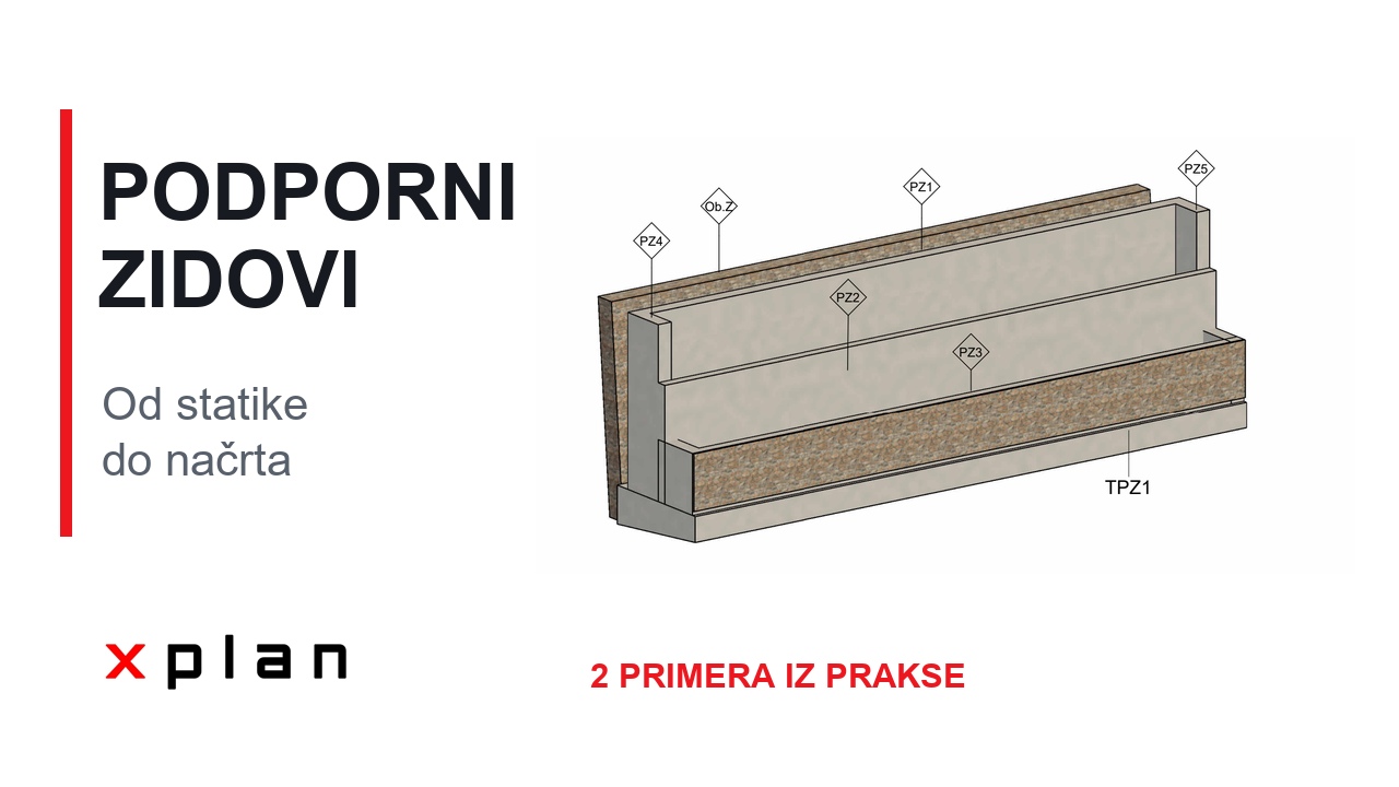
Retaining walls connect the layout of the terrain with the load-bearing structure. At XPLAN, we prepare the structural concept, calculations, formwork drawings and reinforcement drawings. This helps the client understand the proposed solution and gives the contractor coordinated documentation for construction. Two examples from our work show the process from the existing conditions to reinforcement details.
Planning a retaining wall or a change in ground levels? Tell us about your project so that we can identify the information needed for the design.
Retaining walls on video: two project examples
The video has English narration, Slovenian on-screen text and subtitles in six languages. You can also watch it on the XPLAN YouTube channel.
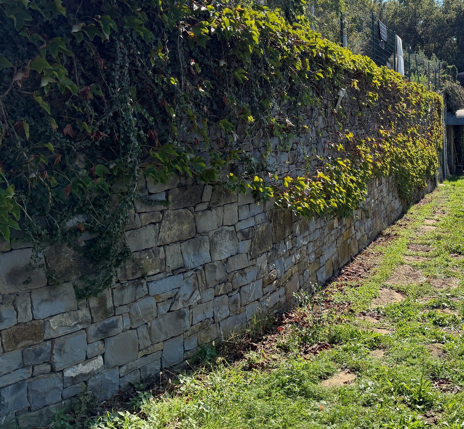
Example A concerns the terrain beside a new building. Example B shows a proposed terraced structure beside an existing stone wall. The photograph records the existing conditions; the drawings and 3D views show the proposed designs. We use anonymous labels to protect our clients’ privacy.
What information does a retaining wall design need?
We first review the terrain, level differences, intended use of the surrounding areas and existing structures. We then consider the available ground information and space for the foundations. Drainage behind the wall is also important. Together, these inputs affect the concept and the calculation assumptions.
PZI construction documentation connects the calculations with the drawings. Formwork drawings define the shape and dimensions of the concrete elements. Reinforcement drawings show the position of meshes, bars and connections. A 3D view helps explain how the walls and foundations fit together.
Example A: retaining walls beside a new building
In the first project, the walls form a platform beside a new residential building and follow the changes in ground level. The concept includes a separate wall and two walls sharing a foundation element. The 3D view explains the stepped arrangement.
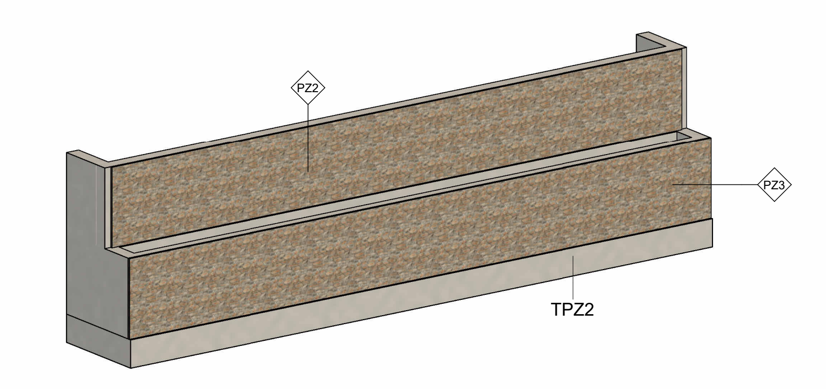
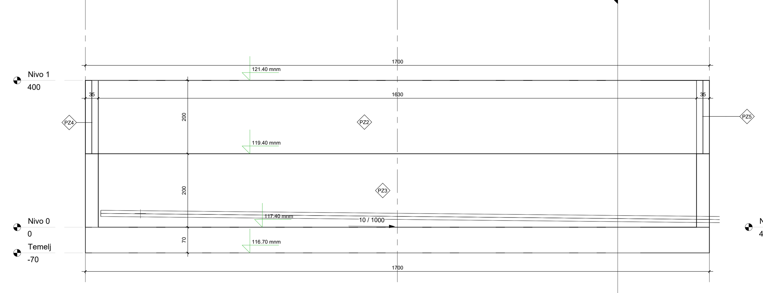
The formwork drawings define the geometry, dimensions and changes in level. Elevations and sections add the measurements needed to understand the shape alongside the details and technical requirements.
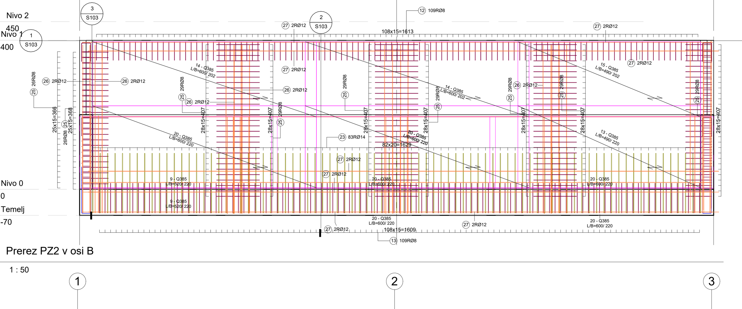
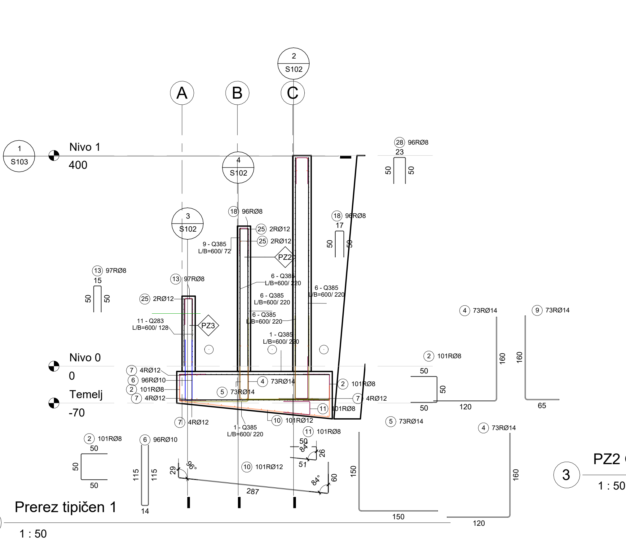
Reinforcement drawings show meshes, bars, spacing and structural connections. The wall-to-foundation connection is particularly important. Read more about this documentation on our reinforcement drawings page.
Example B: a terraced structure beside a stone wall
The second project starts with an existing stone wall. The calculations do not rely on its load-bearing or retaining contribution. The proposed new reinforced concrete structure therefore resists the earth pressures from the ground behind it.
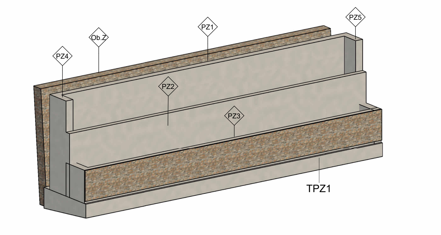
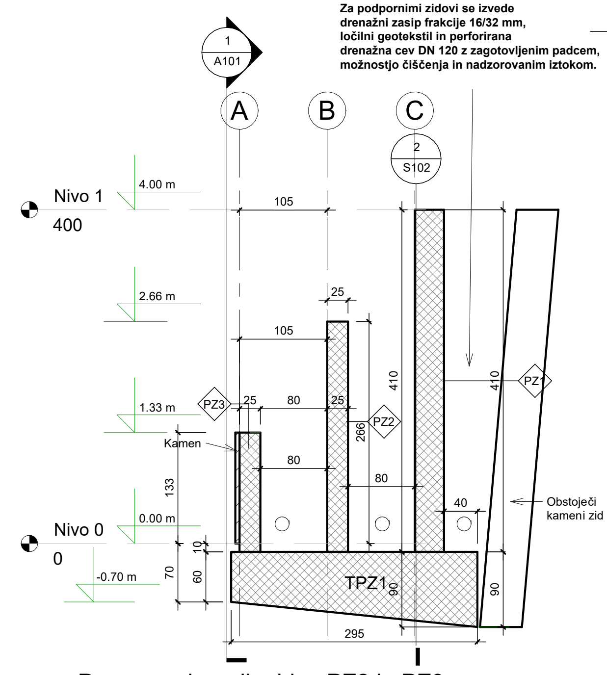
The design consists of three parallel walls on a common foundation slab. The stepped heights create terraces and areas for planting. The 3D view shows the overall arrangement, while the formwork section defines the relationship between the elements.
Structural calculations: earth pressure, stability and foundations
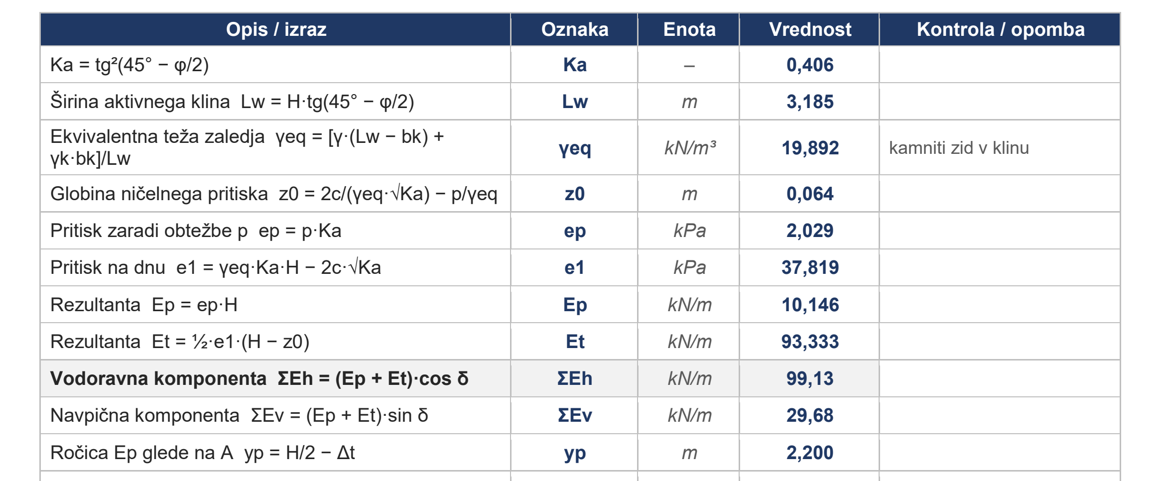
The structural calculations for the second example consider earth pressure and its effects on the structure. The documentation also checks sliding and overturning stability, ground stresses and the design of the reinforced concrete elements.
The results depend on the input assumptions. In this example, the assumed geotechnical parameters must be confirmed by a geotechnical report before construction. If the actual conditions are less favourable, the documentation requires the calculations to be repeated. These extracts therefore cannot be used to size another wall.
For broader technical context, see the European Commission’s introduction to Eurocode 7: Geotechnical design.
Drainage and reinforcement complete the structural solution
Drainage is part of both designs. The documentation specifies drainage backfill, a separating geotextile and pipes with a suitable outlet. The second calculation expressly assumes functioning drainage and does not include hydrostatic pressure. Correct construction and maintenance of the drainage are therefore essential to the intended behaviour.
Reinforcement sections show how the reinforcement continues through the wall-to-foundation connections. Before concrete is placed, the work must be checked against the current project documentation. Any differences between the actual and designed conditions need to be coordinated with the designer.
Planning a retaining wall?
For an initial review, send a short description and photographs of the terrain. Include existing plans and a geotechnical report if available. We can then define the design scope and identify missing information.
Send an enquiry about retaining wall design or email info@xplan.si.
XPLAN | Structural design · Structural calculations · Construction supervision